`timescale 1ns / 1ps
module ride_edge (
        input wire clk,resetn,
        output wire hold_p
    );

    reg hold;
    reg [1:0] count;

    assign hold_p = hold;

    always @(posedge clk or negedge resetn) begin
        if (!resetn) begin
            hold = 0;
            count = 0;
        end
        else begin
            if ( count == 0 ) hold = 1;
            else if ( hold == 1 ) hold = 0;

            count = count + 1;
        end
    end

endmodule
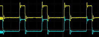
Then probe with oscilloscope.
Then made same code with non-blocking assignment like below.
`timescale 1ns / 1ps
module ride_edge_nonblocking (
        input wire clk,resetn,
        output wire hold_p
    );

    reg hold;
    reg [1:0] count;

    assign hold_p = hold;

    always @(posedge clk or negedge resetn) begin
        if (!resetn) begin
            hold = 0;
            count = 0;
        end
        else begin
            if ( count == 0 ) hold <= 1;
            else if ( hold == 1 ) hold <= 0;

            count <= count + 1;
        end
    end
endmodule
Here is Vivado diagram. The FCLK_CLK0 is 100MHz, xslice_1 pick Din[4] make 3.125MHz clock ( = 100MHz/32 ).
Then probe both hold_p.
Puzzled. I expected that non-blocking will be delayed 1 clock. No wonder as schematic shows exactly same nets generated.
But why no difference between blocking and non-blocking assignment ? I guess that when the design involves a register then assignment type doesn't matter as the register will be used in same manner. It seems Vivado synthesis reads between lines.
Then once you put a register in a design, same sequential logic will be generated which means '<=' will be used on every '='. Then better use '<=' on Verilog to avoid confusion ?
Sequential logic needs register. It seems to me that '<=' is the only choice left.


No comments:
Post a Comment