Computing Memoir

essay on programming languages, computer science, information techonlogies and all.

Monday, July 15, 2024

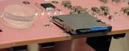
when sd-card holder start to open up

This board has a sd-card for image but after some insert and remove, the holder opens up. When hold tight by finger, it works.


Well, no skill of soldering nor tools available, it is a disaster and make the expensive dev board to go to bin.

But if laundry hanger is nearby, the board can be saved ... at least for a while.


Thursday, July 11, 2024

Fighting aganist optimization

Here is a snippet of verilog code - a simple command decoding module and block ram. It get 32 bit command by rx_data and if the command is memory write, then next command is memory value to store - e.g. command 3100_0004, CAFE_BEEF, 1234_5678 will store CAFE_BEEF, 1234_5678 at block ram address 0x0004.


module top_nerves
    #(  parameter integer CMD_MEM_ADDR_WIDTH = 8
    ) (                        
...
        input [31:0] rx_data,
        input rx_valid,
        output rx_ready,     
...
    );

	wire [23:0] mem_addr;
	wire mem_wstrb;
	wire [31:0] mem_wdata;
	wire mem_wready;
	wire [31:0] mem_rdata;
	wire mem_rstrb;
	wire mem_rbusy;

	cmd_decoder
		cd(
			.clk(clk),
			.rst_n( rst_n ),
		
			.rx_data( rx_data ),
			.rx_valid( rx_valid ),
			.rx_ready( rx_ready ),
...
			.mem_addr( mem_addr ),
			.mem_wstrb( mem_wstrb ),
			.mem_wdata( mem_wdata ),
			.mem_wready( mem_wready ),
			.mem_rdata( mem_rdata ),
			.mem_rstrb( mem_rstrb ),
			.mem_rbusy( mem_rbusy ),

			.io_out( cmd_io_out )
		);

    bram_32bits #(
...        )
        cmd_mem ( 
            .clk( clk ),
            .waddr( mem_addr[CMD_MEM_ADDR_WIDTH-1:2] ), 
            .wdata( mem_wdata ),
            .wenable( mem_wstrb ),
            .raddr( mem_addr[CMD_MEM_ADDR_WIDTH-1:2] ),
            .rdata( mem_rdata ) 
        );        
endmodule


module cmd_decoder (
        input [31:0] rx_data,
        input rx_valid,
        output reg rx_ready,     
		...
        output reg [23:0] mem_addr,
        output reg mem_wstrb,
        output reg [31:0] mem_wdata,
        input mem_wready,
        input [31:0] mem_rdata,
        output reg mem_rstrb,
        input mem_rbusy,
);
	...
    localparam
        CMD_MEM_WRITE = 4'h3,
        ...
    ;
        
    reg [3:0] state;
    reg [31:0] data;
    wire [3:0] cmd;
    assign cmd = data[31:28];
    reg [3:0] cur_cmd;
    
    always @( posedge clk or negedge rst_n ) begin
		...            
            case (state)
                FETCH : begin
                    if (rx_valid) begin 
                        data <= rx_data;
					...
                    end 
                end
                
                LOAD : begin
                    cur_cmd <= cmd;

                    case (cmd)
                        CMD_MEM_WRITE : begin
                            word_count <= data[27:24] + 1; 
                            mem_addr <= data[23:0] - 4;
                            state <= DONE;
                        end
                        ...
                    endcase
                    
                    
                MEM_WRITE : begin
                    if( mem_wready == 1 ) begin
                        mem_addr <= mem_addr + 4;
                        mem_wstrb <= 1;
                        mem_wdata <= data;
                        word_count <= word_count - 1;
                        state <= DONE;
                    end
                end
			
            	...                
            endcase
        end        
    end    


Now when run synthesizing, two missings noted.
- 8 bits of rx_data is missing. [31:0] is mapped to [23:0]. The first 4 bits is for command and second 4 bits for word count.
- mem_wdata is not connected between cmd_decoder and bram. Code has "mem_wdata <= data;" which should connect mem_wdata to bram.


The first puzzle is just wrong assumption that the [31:24] of [31:0] must be removed and mapped to [23:0]. What removed is the address not used - from [23:16] of [31:0]. When hovering over the ... like below, those optimization was revealed.


Second puzzle is from the unassigned wire. The bram in here is such that the mem_wready is not necessary but the top_nerves.v defined it anyway and assigned it.  And optimization figured it out that mem_ready will be 0 always and it removes statements inside. 

module cmd_decoder (
...                  
                MEM_WRITE : begin
                    if( mem_wready == 1 ) begin   // mem_wready is 0 always
                        ...  // optimization just ignore this part completely.
                    end
                end
When put 1 to the wire value, then mem_wdata is correctly synthesized.

module top_nerves
...
	cmd_decoder
		cd(
                        ...
			.mem_addr( mem_addr ),
			.mem_wstrb( mem_wstrb ),
			.mem_wdata( mem_wdata ),
			.mem_wready( 1 ),
			...

Sometimes, the job of programmer is to understand what other program is generating before writing own program. 
Wednesday, June 21, 2023

C++ catches

Can you find a catch at the code below ? Occasionally I see "loop starting ..." then "loop end ..." but no "loop ... ".

class ScopeFeeder
{
public:
    ScopeFeeder() : 
        loop_thread__( [this](){ loop(); } )
    {}

    ~ScopeFeeder()
    {
        stop_ = true;
        loop_thread__.join();
    }
...

private:
    std::thread loop_thread__;
    bool stop_ = false;

    void loop() 
    {
        cout << "loop starting ...\n";
        while( !stop_ )
        {
            cout << "loop ...\n";
...
        }
        cout << "loop end ...\n";
    }
};
s

c

r

o

l

l


d

o

w

n


stop_ can be true when loop() is running obviously. And it can be as initilizaton order matters in here and stop_ has to be initialized first. If you put stop_ in front of loop_thread_, then stop_ is not undefined anymore and loop() will run happily ever after.

class ScopeFeeder
{
...

private:
    bool stop_ = false;              // stop_ first.
    std::thread loop_thread__;

...
};

Wednesday, July 6, 2022

Cross-compile Armv7 from x86_64 using docker

Cross compiling sounds like a big water difficult to cross. Of course it asks a lot of knowledge but at the deep down, it is just another way of compiling and linking. And in here I am trying to show it by cross-compiling raspberrypi target from ubuntu x86_64 machine.

First, you need toolchain - arm gnu toolchain. I used 9.2 as it happended to be the version I used on work.

Second, part of target file system - /usr and /lib. For raspberry pi 32bit, download raspberry pi OS lite at here. Then extract /usr and /lib only.

With these two, we can make docker image for the build. Build needs x86_64 tools. And cross-compiler tool-chain - gcc-arm-xxx-x86_64-arm-xxx. And target root of raspbian os.

# Dockerfile
FROM  ubuntu:20.04

RUN useradd -s /bin/bash -u 1000 docker_user && \
    apt-get update && \
    apt-get install -y \
    gcc g++ cmake git ninja-build lcov bison flex curl python3 fakeroot libpcre3-dev libcurl4-openssl-dev libxml2-dev \
    cppcheck clang-tools clang-format clang-tidy
RUN apt-get install -y python3-pip 

# https://developer.arm.com/downloads/-/gnu-a
# AArch32 target with hard float (arm-none-linux-gnueabih, )
ADD gcc-arm-9.2-2019.12-x86_64-arm-none-linux-gnueabihf.tar.xz /opt

# SYSROOT from rapsbian buster armhf - usr, lib only
ADD raspios-buster-armhf-lite.usrlib.tar.gz /opt/raspios-buster-armhf-lite
RUN ln -s /opt/raspios-buster-armhf-lite/lib/arm-linux-gnueabihf/ /lib/arm-linux-gnueabihf

... snip ...


Third, we needs cmake cross-compiling toolchain file. Below cmake defines the cross-compiling by specifying compiler - gcc-arm-xxx - and include and lib path at /opt/raspios-xxx. You may wonders why is there no CMAKE_SYSROOT, CMAKE_FIND_ROOT_PATH. I found those generate number of error that ask other changes which seems to be too obscure to pursue. And I think it is succinct to tell the tool-chain where to look at to compile and link instead of using those magic words.

# toolchain_raspberrypi_gcc9.cmake

set(CMAKE_SYSTEM_NAME Linux)
set(CMAKE_SYSTEM_VERSION arm)
set(CMAKE_SYSTEM_PROCESSOR arm-linux-gnueabihf)
set(CMAKE_C_COMPILER /opt/gcc-arm-9.2-2019.12-x86_64-arm-none-linux-gnueabihf/bin/arm-none-linux-gnueabihf-gcc)
set(CMAKE_CXX_COMPILER /opt/gcc-arm-9.2-2019.12-x86_64-arm-none-linux-gnueabihf/bin/arm-none-linux-gnueabihf-g++)

set(CMAKE_EXE_LINKER_FLAGS "${CMAKE_EXE_LINKER_FLAGS} -L/opt/raspios-buster-armhf-lite/usr")
set(CMAKE_EXE_LINKER_FLAGS "${CMAKE_EXE_LINKER_FLAGS} -L/opt/raspios-buster-armhf-lite/usr/lib")
set(CMAKE_EXE_LINKER_FLAGS "${CMAKE_EXE_LINKER_FLAGS} -L/opt/raspios-buster-armhf-lite/usr/lib/arm-linux-gnueabihf")

include_directories(BEFORE 
    /opt/raspios-buster-armhf-lite/usr/include
    /opt/raspios-buster-armhf-lite/usr/include/arm-linux-gnueabihf


With above cmake toolchain file, we can define remainging part of docker that prepares google unittest and google benchmark.

# Dockerfile
...
ADD toolchain_raspberrypi_gcc9.cmake .

RUN git clone https://github.com/google/googletest.git --depth 1 --branch release-1.11.0 &&\
    cd googletest &&\
    cmake -S . -B ./build_x86_64 &&\
    cmake --build ./build_x86_64 &&\
    cmake --install ./build_x86_64 &&\
    cmake -S . -B ./build_arm -DCMAKE_TOOLCHAIN_FILE=../toolchain_raspberrypi_gcc9.cmake &&\
    cmake --build ./build_arm &&\
    cmake --install ./build_arm --prefix /opt/raspios-buster-armhf-lite/usr/ &&\
    cd ../ &&\
    rm -rf googletest

ADD CMakeLists.benchmark.txt .

RUN git clone https://github.com/google/benchmark.git --depth 1 --branch v1.6.1 && \ 
    cd benchmark &&\
    mv ../CMakeLists.benchmark.txt ./CMakeLists.txt &&\
    cmake -S . -B ./build_x86_64 -DCMAKE_BUILD_TYPE=Release -DBENCHMARK_ENABLE_GTEST_TESTS=0&&\
    cmake --build ./build_x86_64 --config Release &&\
    cmake --install ./build_x86_64 &&\
    cmake -S . -B ./build_arm -DCMAKE_BUILD_TYPE=Release -DBENCHMARK_ENABLE_GTEST_TESTS=0 -DCMAKE_TOOLCHAIN_FILE=../toolchain_raspberrypi_gcc9.cmake &&\
    cmake --build ./build_arm &&\
    cmake --install ./build_arm --prefix /opt/raspios-buster-armhf-lite/usr/ &&\
    cd ../ &&\
    rm -rf benchmark


After you generate docker image, you can go in the image, and make the host build and cross-compile build.

$ docker run --rm -it -v "$PWD":/du -w /du -u 0 samplecpp_build:0.1

/du# rm -rf ./build_x86_64
/du# cmake -S . -B ./build_x86_64
/du# cmake --build ./build_x86_64

/du# rm -rf ./build_arm
/du# cmake -S . -B ./build_arm -DCMAKE_TOOLCHAIN_FILE=../toolchain_raspberrypi_gcc9.cmake
/du# cmake --build ./build_arm


Cross-compiling means you specify compiler and include and lib path. And that is all.

You can find the code at my gitlab project samplecpp

Sunday, March 27, 2022

Annotated Verilog code for AXI-Stream FIFO interface

At Zynq, there is AXI-Stream FIFO to send/receive data between Processor and FPGA. It has two separate FIFOs - one for transmitting data to FPGA and receiving from FPGA. Here I will explain verilog code that can interface the FIFO with annotation.

First the module named decoder needs ports definitions. FIFO TX ports will be received by RX ports - rx_data, rx_valid, rx_ready. You can define special property - ( * X_INTERFACE_INFO ... *) - to group related ports which allows you to connect group ports - AXI_STR_TXD to RX. And TX to AXI_STR_RXD.  


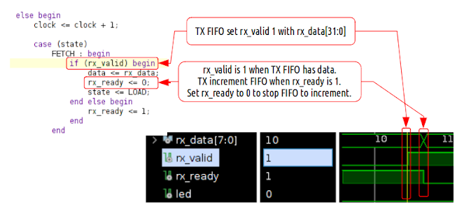
In here, the FIFO data is treated as instruction. And FSM is implemented with FETCH-LOAD-(TX)-DONE cycle. 


When the module get reset_n - active low reset, the FSM get initialized. It can receive data from TX FIFO but no data to send to RX FIFO. 


At FETCH, when TX FIFO is 1, read rx_data.   


At LOAD, if instruction is CMD_WRITE, turn on/off led. If CMD_READ, prepare tx_data for send to TX FIFO 


At TX, send tx_data.  At DONE, we are ready to receive but nothing to send.


For the complete code, refer below.


Sunday, February 6, 2022

Blocking vs non-blocking assignment on sequential logic

Made counter that hold 1 clock at every 4 clock. First with blocking assignment


`timescale 1ns / 1ps
module ride_edge (
        input wire clk,resetn,
        output wire hold_p
    );
    
    reg hold;
    reg [1:0] count;
    
    assign hold_p = hold;
    
    always @(posedge clk or negedge resetn) begin
        if (!resetn) begin
            hold = 0;
            count = 0;        
        end
        else begin         
            if ( count == 0 ) hold = 1;    
            else if ( hold == 1 ) hold = 0;
            
            count = count + 1;
        end    
    end
    
endmodule


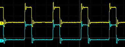
Then probe with oscilloscope.


Then made same code with non-blocking assignment like below.

`timescale 1ns / 1ps
module ride_edge_nonblocking (
        input wire clk,resetn,
        output wire hold_p 
    );
    
    reg hold;
    reg [1:0] count;
    
    assign hold_p = hold;
    
    always @(posedge clk or negedge resetn) begin
        if (!resetn) begin
            hold = 0;
            count = 0;        
        end
        else begin         
            if ( count == 0 ) hold <= 1;    
            else if ( hold == 1 ) hold <= 0;
            
            count <= count + 1;
        end    
    end    
endmodule


Here is Vivado diagram. The FCLK_CLK0 is 100MHz, xslice_1 pick Din[4] make 3.125MHz clock ( = 100MHz/32 ).


Then probe both hold_p.


Puzzled. I expected that non-blocking will be delayed 1 clock. No wonder as schematic shows exactly same nets generated.


But why no difference between blocking and non-blocking assignment ?  I guess that when the design involves a register then assignment type doesn't matter as the register will be used in same manner. It seems Vivado synthesis reads between lines.   

Then once you put a register in a design, same sequential logic will be generated which means '<=' will be used on every '='. Then better use '<=' on Verilog to avoid confusion ?  

Sequential logic needs register. It seems to me that '<=' is the only choice left. 
 

Wednesday, July 7, 2021

Finding planar rigid tranformation - linearized and weighted least squares

Rigid Transformation

A point P in the world can be expressed as Body coordinate as well as World coordinates, and the relationship between the two are rigid transformation - rotation and translation - like below.


Refer Wiki - Kinematics : Matrix representation

Image resolution and dimension

A point at an image can be expressed on world coordinates using Image resolution - i.e. mm / pixel - and dimension. At below, resolution is r. W is width and H is Height. Point at center (0,0) will be (320,240) of 640x480 image.


Geometric Model

For example, there is a pixel point (P) on a camera ( C ), that is offseted ( CO ) and assmebled to a machine (W).


And the machine has a stage (S) and it is moved by motor (M) and the stage has a point.


Then any point that camera see can be matched to a point on the stage.


Least square method on a linearized transformation matrix

If we know all other transformation except camera offset, then we can rearrange above equation like below for an i-th point.


The unknown CO transformation matrix can be linearized in assumption that the angle is small.


Then the equation can be rearranged putting the unknown X on right. Then the unknown can be solved by matrix inversion. Refer Wiki - Least Square : Linear least squares


Weighted least square method

If there is an uncertainty on each measurment of pixel point, the uncertainty can be put as weight (W) on each pixel point.


Then the equation can be rearranged for the unknown X. Note that element of X changed sign for convenience.